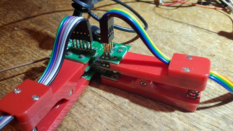
[Martin] sent this query, along with the lead photo, into the tip line, and he makes a good point. Most development and evaluation boards have multiple rows of pin headers, often arriving loose in the package — soldering is left to the user. In an abundance of caution, we usually design our prototype boards with many pin headers for debugging and testing. But as [Martin] reminds us, there are other alternatives to solder.
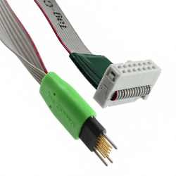
- Yours truly once worked with a prolific designer of PIC microprocessor boards. Long before the advent of solutions like the Tag Connect family, [Ralph] would program his boards by just inserting a pin header into the PCB and applying gentle pressure with his thumb until the code finished flashing.
- You may have seen the staggered offset PCB patterns that hold your pin header securely while you solder. You could tweak this a little bit to put more pressure on the pins, making a solder-less connection that is sufficient for temporary testing.
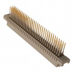
- Taking the opposite approach, you can get solderless connectors with press-fit pins, a method we tested a few years ago on a Raspberry Pi Zero. Anyone who has worked on Eurocard-based systems like VME can appreciate the time-savings and improved reliability of 96-pin DIN-41612 press-fit connectors.
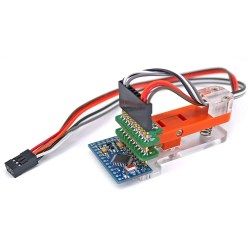
- Or, as [Martin] proposes, you could use one of these inexpensive pogo-pin clamps. These are available for less than $10 from your favorite Asian electronics distributor. They are about the size of a large clothespin, and are available in several different pin configurations.


These techniques won’t help you if you need to plug your board into another card, such as a hat onto a Raspberry Pi. But when you just want to grab a few signals for a serial port or probing some digital I/O signals, having a few of these clips in your tool box can save you the time and headache of soldering down a header. Do you have any tips for making soldering pin headers easier, or even avoiding them altogether? Let us know in the comments below.
0 Commentaires