I have a confession to make. I write about a lot of projects for Hackaday, but there are very few I read about and then go actually build a copy of it. I don’t have a lot of time and I’m usually too busy building my own stuff. But once in a while, something strikes my fancy and I’ll either raid the junk box or buy the kit. The most recent case of that was the PX-41C, a replica of the classic HP-41C.
The HP-41C is a somewhat legendary reverse-polish notation calculator. I still have my original HP-41C from 1979 (a very low serial number). It is still a workhorse but at 43 years old or so, I don’t like to leave it hanging around or near anything that might damage it. It has enough wear from the daily use it received 40 years ago. Sure, I have great emulation on my phone and I use that too, but the PX-41C kit looked fun, and with all through-hole parts it would be a quick build. The black Friday sale on Tindie sealed the deal for me.
Start-Up
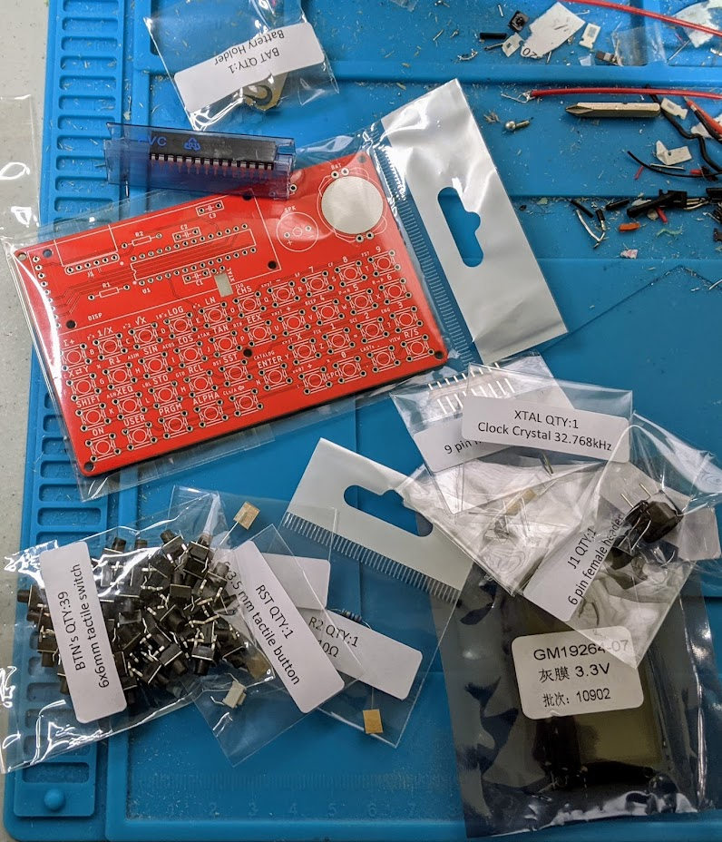
The kit arrived on the Saturday after Thanksgiving, I decided to tackle it while waiting for some 3D prints. The components were all nicely bagged and marked. Tearing into the bags was a bit frustrating, but not hard and it did keep everything separate. There was a bill of materials, but — I thought — no instructions. Turns out the last part of the bill of materials is a link to some instructions. They aren’t much and I didn’t realize they were until after completing the board, but it isn’t hard to figure out. All the parts are marked on the silkscreen and you can probably figure it out — with a few caveats.
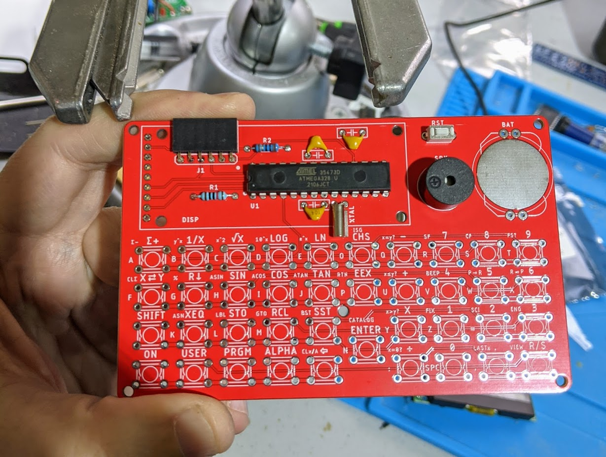
Several components go under the LCD display and that is soldered in, so you need to put them in first. I wondered if you should install them on the back of the board, but the pictures showed them front-mounted and you realize pretty quickly you have to bend them down to let the LCD sit flat. The instructions, if you read them, do mention this.
Once I had everything but the switches done, I powered up to make sure it all worked. It did — or, at least — it powered up and said MEMORY LOST.
Switches
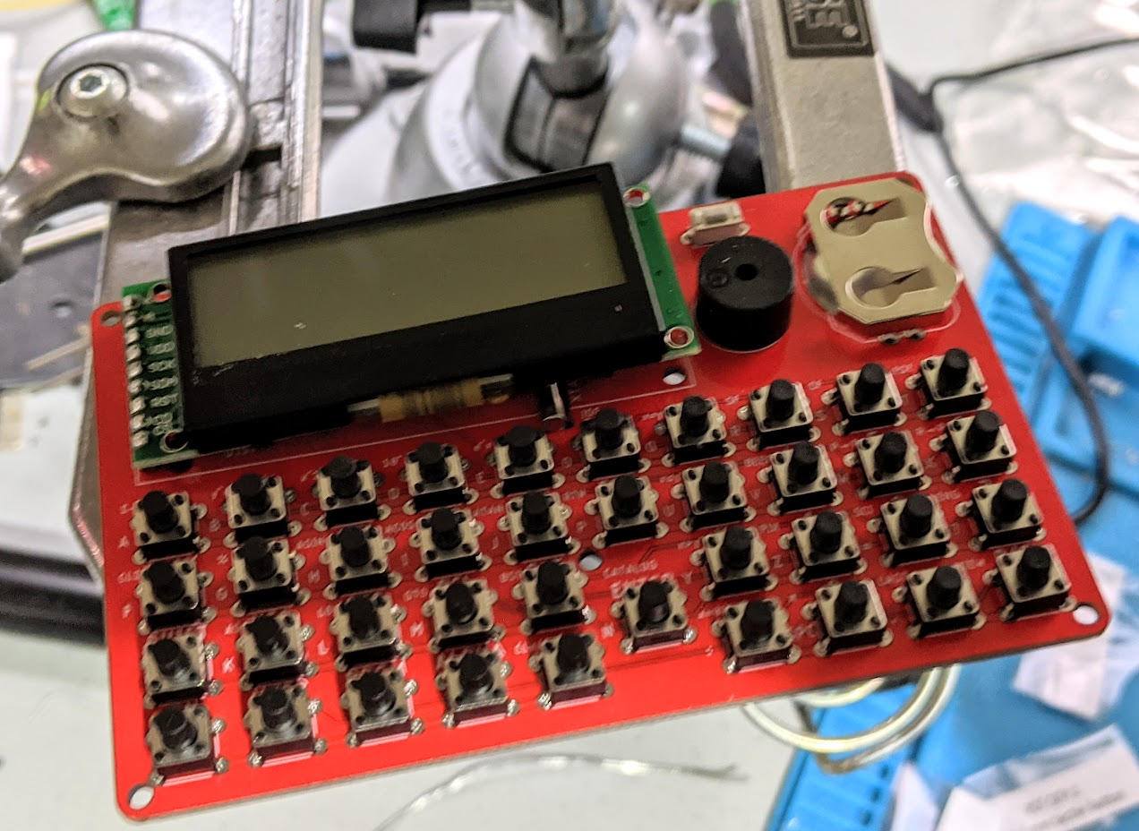
There are 39 little tact switches to install. Luckily, they have little legs that spring into the holes, so it isn’t very hard. However, they can pop out, so I suggest doing a column or two at a time. One switch was a little bent out of shape but there was an extra, so I didn’t bother trying to unbend it.
With a few keys in the bottom right corner, I could power on and do a few quick calculations with no problem. The board takes a CR2025 and I only had a thinner battery. A dime made a good spacer and let me fit the thin battery and get the thing working.
Configuration
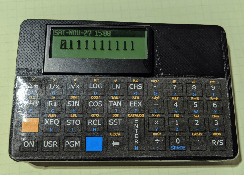
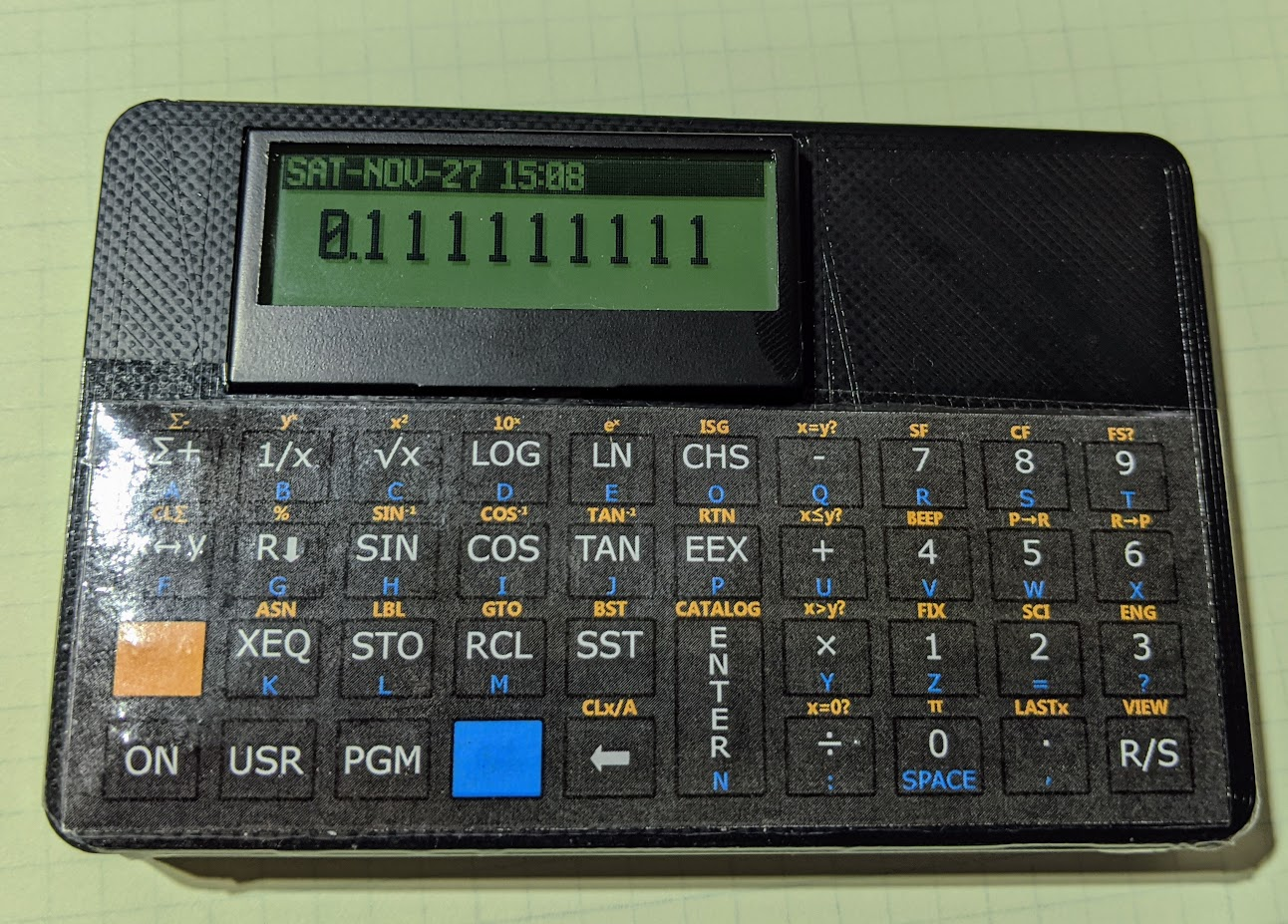
The board has a backlit LCD and a clock — features a regular HP41C didn’t have. However, I didn’t see an obvious way to set them. I had found the documentation by then and it said to hold the 0 key while powering on to get into the configuration menu. Turns out, it is the divide key, which took a minute to figure out. In addition, the keys to operate the menu system are a little wonky (but, in all fairness, the firmware put a help message on the screen until you release the divide key).
Just in Case
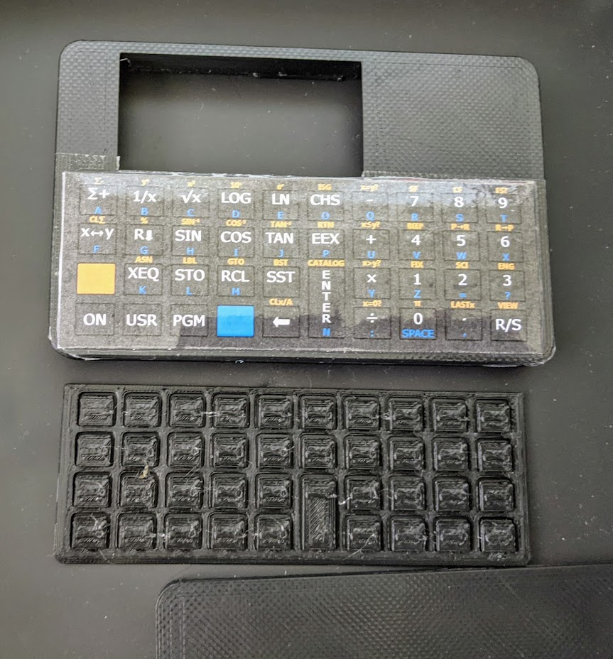
There is a 3D printed case and a way to print an overlay for the keys along with a springy key matrix. They were nice enough to send me these already made up, although I’m not sure that’s always included. The overlay looks great at first, but if you look closely, it is taped down and that detracts a little from it. Don’t lift up the tape! It will ruin the overlay.
The case looked good, and it is fairly simple. There were a few problems, though. First, the LCD was poking up at an angle. The instructions tell you to tape it down to the CPU, but that didn’t really help. After taking these pictures, I pulled the LCD off and reinstalled it carefully with new headers and had it come out nice and flush.
The other problem was that the R/S key in the bottom right corner didn’t want to work with the case in place. Sometimes it was inoperative. Sometimes it would work but didn’t click like the rest of the keys and was more like a touch panel. Sometimes it was stuck pressed down.
I tried filing the case a little but that didn’t seem to help. There are some nubs that keep the board from coming down too low on the key springs. It looks like the case was warped enough to have that corner a bit lower than the rest. If you left the back off and pushed on that corner, it would reproduce the problem, but the other corners were fine.
I thought about reprinting the case myself — I have enough 3D printers, after all. But I finally made a little paper shim to make the stop in that corner a little thicker. I just took a small strip of paper and folded it many times until it was about the same size as the stop and inserted the stop into the paper making a sandwich where the paper was the bread and the stop was the meat. This seems to have cleared up the keyboard issue. It doesn’t look like the problem was related to the key installation, but anything is possible. I’m pretty sure it was just a subtle warping in the case.
Last Impressions
For the price (about $40) this is a fun kit and is actually useful. It would be nice if the LCD had a socket. It would also be nice if the overlay install looked cleaner, but for a casual glance, it is fine and it still looks better than just a bare PCB with keys — unless you like that sort of thing.
I haven’t tried to see if the emulator will do synthetic programming yet, but it is on my to do list. Otherwise, I now can use my HP41C with no phone and without risking my real one. After forty-some-odd years, it can use the rest.
For some reason, the projects I tend to build after writing (or reading) about them are mostly for retrocomputing. I built the KIM UNO (and repurposed it for the 1802). I built a PiDP-8 (and need to find time for the PDP-11 version). Possibly my favorite was the $4 Z80 which I actually added a bit to, software-wise.


![[Thomas Sanladerer] Gets New Threads](https://lh3.googleusercontent.com/blogger_img_proxy/AEn0k_vIKp1SHPlxqh5wiUhaMpdUXNQ9sxn9kRTqo15VtVS5pHJkNAWvr5nPJIZaKyAdvuiX96z7VAoqdlg209dJA416F346BwT1J2gAbuSv7_EJxSdjBwzei8wKuXh2IuK0oS-FzWg=w680)


0 Commentaires