Like a lot of Hackaday readers, I pride myself on being “the fix-it guy” in my family. When something breaks, I get excited, because it’s a chance to show off my skills. It’s especially fun when something major breaks, like the fridge or the washing machine — repairs like that are a race against time, since I’ve got to get it fixed faster than it would take to hire someone to do it. I usually win the race; I can’t remember the last time I paid someone to work on something. Like I said, it’s a point of pride.
And so when my son came home on Thanksgiving break from his first semester away at college, eager to fire up his Xbox for some mindless relaxation from his biochemistry studies, only to be greeted with a black screen and no boot-up, it was go-time for me. I was confident that I’d be able to revive the dead box in time for him to have some fun. The fact that he’s back at school and the machine is still torn apart on my bench testifies to my hubris, but to be fair, I did get close to a fix, and may still yet get it done. But either way, the lessons I’ve learned along the way have been really valuable and worth sharing.
Diagnosis
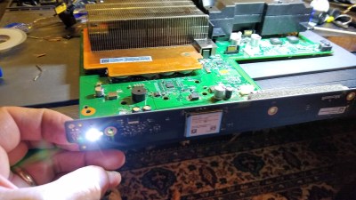
Right off the bat, this looked like a power problem — plug it in, press the button, no LED, no beep, no fan. We checked the basics, like making sure there was line voltage at the end of the power cord and wiggling things around to find loose connections. With those eliminated, I decided that it might be a bad power supply, which on the Xbox One X is an internal module. With teardown instructions at hand, we pulled the power brick out of the case and tested it — 12 V, just like the label says. Too bad — that would have been a simple fix.
A little bit of Googling led me to a series of repair videos that seemed to match the symptoms. One in particular caught my eye; it suggested that a bad HDMI retimer chip could be the culprit. Exactly how this chip would have gone bad was a mystery — the console was largely unused for months — as was how a bad HDMI chip could disable a whole machine. But it was a lead.
Unfortunately, the fix for this problem was far outside my wheelhouse. I’m skilled with a soldering iron, but only in the macroscopic world. Yes, I’ve tried surface-mount device soldering before, going so far as to enter the SMD Challenge at the 2019 Superconference. I didn’t exactly cover myself in glory, but I did well enough with the suboptimal tools on hand at the Supercon that I thought I could probably do a decent job. But first, I’d need to go shopping.
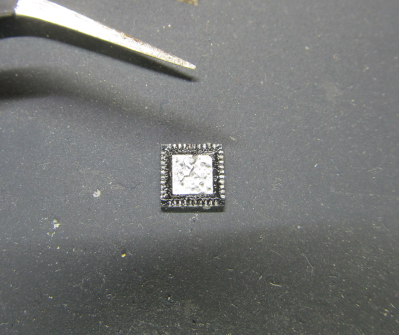
The chip I needed to replace was a TDP158, which comes in a 40-pin quad-flat no-leads (QFN) package. I don’t know much about SMD, but this is clearly a package that can’t be tackled with just a soldering iron. The lands on the underside of the case have a 0.4 mm pitch, and there’s a relatively huge thermal transfer pad that gets soldered to the board. I would need some tools to make the repair possible.
While I was willing to plunk down $55 for a cheap hot-air station on Amazon, I wasn’t ready to shell out for the other tool I’d obviously need: a microscope. I figured — unwisely, as it turns out — that I’d be able to muddle through the repair with the simple head-mounted magnifiers Bil Herd suggested to me back when I explored the issues of getting old as a hacker. The other thing I’d need was a replacement TDP158, which is carried by both Mouser and Digi-Key. Unfortunately, they were both out of stock, with estimated delivery in March — of 2023! Luckily, resellers on Amazon had them in stock, so I added one to my order and completed the teardown while waiting for delivery.
First Repair Attempt
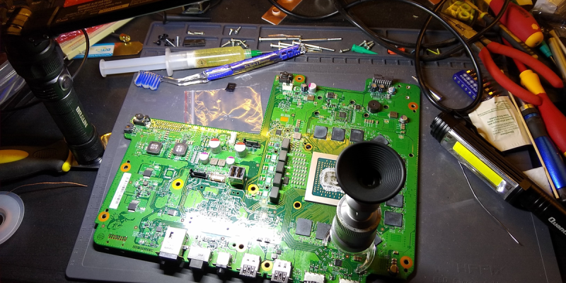
Getting the putatively defective chip off the board was actually easier than I thought it would be. The videos I had watched all had their hot-air stations cranked up to 480°C — that big thermal pad on the back on the QFN really sinks the heat well. It also helps when the chip is being replaced, and you don’t really care how much heat you’re blasting into it. That would come to haunt me later, but for my first go, all I was concerned with was not melting off any nearby caps and resistors, for which I had no spares.
Where I started running into trouble was once the chip was popped free. There’s a big pad underneath which is obviously connected to a lot of copper, because trying to tin it was a nightmare. Just rubbing it with the tip of my Hakko iron wasn’t enough, even with the heat cranked up to the max — the solder would instantly harden and form bumps that would keep the chip well above the surface of the board. And when I used desoldering braid to try to suck away the excess, the braid would just end up soldered to the pad. It took a combination of hot air and soldering iron to get the pads in shape and ready for the new chip.
Everything I had seen on reflow work led me to believe the hard part was behind me; at this point, flux, the solder resist on the board, and the miracle of surface tension would just magically float the chip into the right position with the application of a little heat. And it sort of did, but even through my janky magnifiers, I could see there were problems. The pads along one edge of the chip clearly didn’t have much solder on them, and there were a few obvious solder bridges.
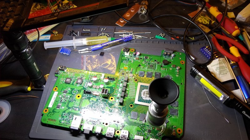
What ensued was literally hours of chasing solder around the board with hot air, my soldering iron with just about every tip I could find to try, several milliliters of flux, and a hell of a lot of swearing. Also a lot of tool changes, especially in the optics department. The head-mounted peepers weren’t enough, so I found a little stand microscope that I could sort of balance above the chip to get a look at the joints. My lighting was also atrocious — I had enlisted my handy Harbor Freight rechargeable work light, which really helped, but it still cast awkward shadows and was in the way of my tools most of the time.
Some Success
I eventually got sick of chasing solder around, and when I was convinced that I had at least taken care of the solder bridges, I plugged enough stuff back together to give the console a test. To my complete astonishment — especially since my son was now watching the proceedings — it booted right up! But alas, when buttoned up and tested on the TV, there was no HDMI output — those solder-starved joints, no doubt. On to round two.
The second time went a little easier thanks to the experience of round one. I popped the chip off, cleaned up both it and the pads, and floated the chip back into position. This time there were no bridges, and all the joints looked bright and shiny — could it be? Did I finally fix it?
Of course not — it wouldn’t even boot this time. I suspect I just plain cooked the chip — between all the solder chasing of the first attempt, and the resoldering of the second try, I dumped a ton of heat into the poor thing and just did it in.
Third Time’s a Charm?
That’s where things stand now, and while I wait for another chip so I can give it a third try, all I can do is look at the lessons I’ve learned. While it’s a poor craftsman who blames his tools, there’s still something to be said for a proper setup. I really need a microscope if I’m going to get serious about this. [Scotty Allen] of [Strange Parts] sings the praises in this video about his microscope, so I might pick up something along those lines. Then again, there are some microsoldering pros who swear by the video-only approach. (Video, naturally.) I think a stereo microscope seems more like my speed, though.
Lighting is another big concern. The scope I’m looking at has a coaxial ring light for shadow-free illumination, but the room lighting in my shop needs an overhaul. Granted, it was built with writing in mind and has mostly task lighting, but being able to dump a lot of light when I need it would be a good idea.
Finally, what I need most is practice. I’ll probably pick up some SMD practice kits, and perhaps some old e-waste to practice desoldering on.
Did I miss anything? Tell us about it in the comments. I’m especially keen to hear about everyone’s experiences climbing the learning curve, especially from old-timers.


![[Thomas Sanladerer] Gets New Threads](https://lh3.googleusercontent.com/blogger_img_proxy/AEn0k_tQK6fSw6DmC0j8DYMNk_Lpjr8lXXIJoYwSJQbSBjcB5PfAOGILGmhX4-3ZcuaYjycBTYPyIHBH_VUJ3ag16UwdMcZjpM19IlqPZ7AAw6GVGcs_cfCup7Pg8Yu3I8uEU5VaIIM=w680)


![[Thomas Sanladerer] Gets New Threads](https://lh3.googleusercontent.com/blogger_img_proxy/AEn0k_tQK6fSw6DmC0j8DYMNk_Lpjr8lXXIJoYwSJQbSBjcB5PfAOGILGmhX4-3ZcuaYjycBTYPyIHBH_VUJ3ag16UwdMcZjpM19IlqPZ7AAw6GVGcs_cfCup7Pg8Yu3I8uEU5VaIIM=w100)
0 Commentaires