
In an ideal world, your FDM 3D printer’s bed would be perfectly parallel with the print head’s plane of movement. We usually say that means the bed is “level”, but really it doesn’t matter if it is level in the traditional sense, as long as the head and the bed are the same distance apart at every point. Of course, in practice nothing is perfect.
The second best situation is when the bed is perfectly flat, but tilted relative to the print head. Even though this isn’t ideal, software can move the print head up and down in a linear fashion to compensate for the tilt. Things are significantly worse if the bed isn’t itself flat, and has irregular bumps up and down all over.
To combat that, some printer firmware supports probing the bed to determine its shape, and adjusts the print head up and down as it travels across the map. Of course, you can’t probe the bed at every possible point, so the printer will have to interpolate between the measured reference points. Marlin’s bilinear bed leveling is an example.
But if you have enough flash space and you use Marlin, you may want to try unified bed leveling (UBL). This is like bilinear leveling on steroids. Unfortunately, the documentation for this mode is not as plain as you might like. Everything is out there, but it is hard to get started and information is scattered around a few pages and videos. Let’s fix that.
The Basic Idea
The idea is simple. The printer probes the bed at many spots. Ideally, you use some sensor to do this that isn’t too far away from your print head. You can have up to 225 points, although 100 or 49 are common sizes — that is, 15 x 15, 10 x 10, or 7 x 7 and the bed doesn’t have to be square. The firmware stores the probe values in EEPROM. In fact, it can store more than one mesh, which is useful if you have multiple print surfaces: you might store a mesh for a glass bed in one slot and one for a PEI bed in another, for example.
Once the probe data is in place, you shouldn’t have to probe it again, at least for a long time. However, there are a few possible issues. First, your bed might not probe exactly right in every spot. Even more likely, your probe may not be able to reach every spot on the bed that the nozzle can. Finally, things change over time. Your bed may sink a little on its mounts. The system can adapt to everything, but it is a bit complex until you get used to it.
Everything Old is New Again
Of course, bed leveling isn’t exactly new technology. Printers have had the capability to do some version of it for a long time. If your bed is perfectly flat, it might be sufficient to just tilt the virtual bed. This is common with, say, glass surfaces, where it is feasible to just figure out the slope of the X and Y tilt and apply it linearly.
UBL is a bit different. It uses many points and interpolates linearly between each set of points. Imagine each measurement point as being part of a larger grid. As the print head moves in the grid, the printer adjusts based on the slope of the imaginary lines connecting the nearest grid point to its neighbors.
But it is more than just the many points that makes UBL different. First, UBL allows you to fine-tune points easily. Since the correction between points is just a guess, there are cases where the guess is wrong and you need to edit the point to give more or less correction to a particular spot.
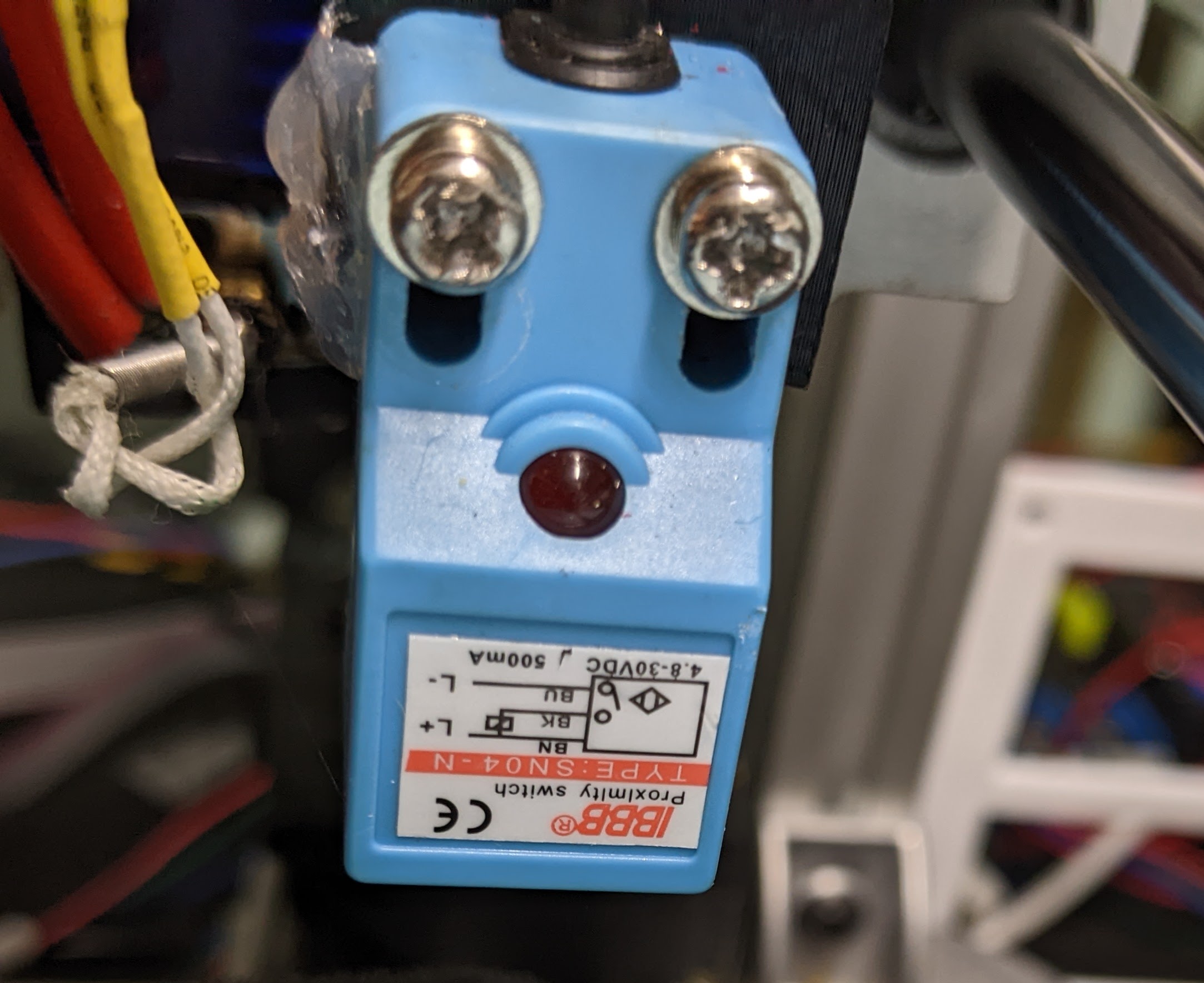
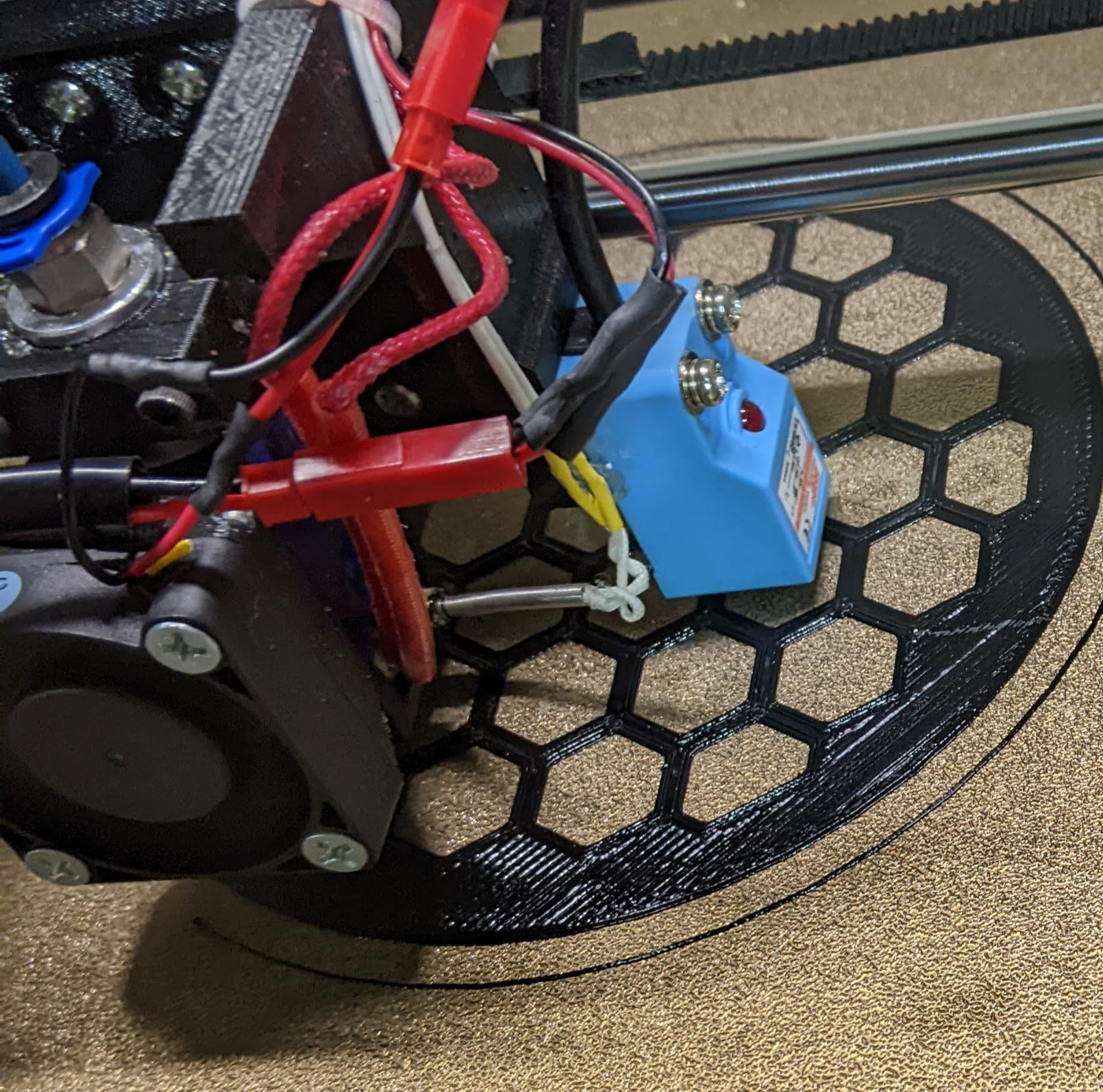
There are several ramifications to this editing that might not be obvious at first glance. For one, you can set up UBL with no Z probe at all. Sure, it is a pain, but you can manually measure all the points and the printer has provisions for helping you make that measurement. Ideally, though, you’ll have a Z probe of some sort. Inductive probes are popular as are BL-Touch and its many imitators. The photo shows a typical inductive sensor.
The other thing editing can do for you is to set points that your Z probe can’t reach. Most probes have some offset from the print head and can’t reach every point the print head can. For example, if the probe is 10 mm to the right of the head and the head can only go to 0 mm, then the probe can only measure X coordinates of 10 mm or greater.
It turns out, if your bed is pretty consistent, you may not have to measure these extra points, but you can if you need to. Marlin is pretty good at guessing the missing values and even if it is wrong, it might be easier to start with the guess and then make adjustments.
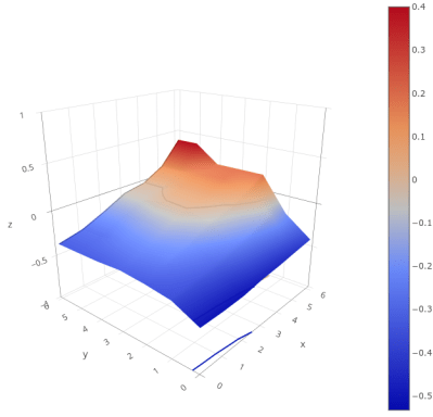
One interesting side effect is that once you have a mesh, there are a variety of ways to visualize what your bed looks like. Then you might want to adjust your bed to be flatter, but if you do you will have to rebuild your mesh. I’ll show you a few ways to get a plot like this next time.
Building UBL
You should already know how to build Marlin for your machine. If not, you’ll have to start there. Once you can get Marlin to build normally, you’ll need to deal with these configuration parameters:
In configuration.h (with some added comments for clarity):
#define AUTO_BED_LEVELING_UBL  // and turn off or remove other AUTO_BED_LEVELING_* defines
#define RESTORE_LEVELING_AFTER_G28 // pick one of these if you want Home to restore level or turn it on
//#define ENABLE_LEVELING_AFTER_G28

//#define PREHEAT_BEFORE_LEVELING // you can enable this section or just preheat manually
#if ENABLED(PREHEAT_BEFORE_LEVELING)
#define LEVELING_NOZZLE_TEMP 120 // (°C) Only applies to E0 at this time
#define LEVELING_BED_TEMP 50
#endif

#define MANUAL_PROBE_START_Z 0.2 // Manual probes will start here so if this value is large, you will waste a lot of time

#define ENABLE_LEVELING_FADE_HEIGHT // When to fade leveling effect to zero (10mm is good)
#if ENABLED(ENABLE_LEVELING_FADE_HEIGHT)
#define DEFAULT_LEVELING_FADE_HEIGHT 10.0 // (mm) Default fade height.
#endif

#define SEGMENT_LEVELED_MOVES // split moves into small pieces instead of entire grid
#define LEVELED_SEGMENT_LENGTH 5.0
// This section sets the parameters for the mesh validation pattern if you want to use it
#define G26_MESH_VALIDATION
#if ENABLED(G26_MESH_VALIDATION)
#define MESH_TEST_NOZZLE_SIZE 0.4 // (mm) Diameter of primary nozzle.
#define MESH_TEST_LAYER_HEIGHT 0.2 // (mm) Default layer height for G26.
#define MESH_TEST_HOTEND_TEMP 205 // (°C) Default nozzle temperature for G26.
#define MESH_TEST_BED_TEMP 60 // (°C) Default bed temperature for G26.
#define G26_XY_FEEDRATE 20 // (mm/s) Feedrate for G26 XY moves.
#define G26_XY_FEEDRATE_TRAVEL 100 // (mm/s) Feedrate for G26 XY travel moves.
#define G26_RETRACT_MULTIPLIER 1.0 // G26 Q (retraction) used by default between mesh test elements.
#endif

#elif ENABLED(AUTO_BED_LEVELING_UBL)  // settings for UBL
//#define MESH_EDIT_GFX_OVERLAY // Display a graphics overlay while editing the mesh
#define MESH_INSET 0 // Set Mesh bounds as an inset region of the bed -- to avoid clips or other margins
// Set the # of rows/columns to use
#define GRID_MAX_POINTS_X 7 // Don't use more than 15 points per axis, implementation limited.
#define GRID_MAX_POINTS_Y GRID_MAX_POINTS_X
//#define UBL_HILBERT_CURVE // Use Hilbert distribution for less travel when probing multiple points
#define UBL_MESH_EDIT_MOVES_Z // If you turn this off, the nozzle could scrape the bed while moving between edit points
#define UBL_SAVE_ACTIVE_ON_M500 // Save the currently active mesh in the current slot on M500
//#define UBL_Z_RAISE_WHEN_OFF_MESH 2.5 // You can force a height when there is no data for a point

#define UBL_MESH_WIZARD // add a wizard for setup to the menu

// more menu setup
#define LCD_BED_LEVELING
#if ENABLED(LCD_BED_LEVELING)
#define MESH_EDIT_Z_STEP 0.025 // (mm) Step size while manually probing Z axis.
#define LCD_PROBE_Z_RANGE 4 // (mm) Z Range centered on Z_MIN_POS for LCD Z adjustment
#define MESH_EDIT_MENU // Add a menu to edit mesh points
#endif

// What do do after a Z probe
#define Z_PROBE_END_SCRIPT "G1 Z10 F12000\nG1 X15 Y200\nG1 Z10"
There are also a few settings in configuration_adv.h if you need to override, for example, the three-point probe corners and things like that. You can usually leave these alone. If you have an 8-bit controller, you may not have enough memory to build UBL. There are a few ways to reduce the memory footprint, but not by much. Better to upgrade to a larger board.
Next Time
Once you have the firmware built and downloaded to your printer, you are ready to go, right? Not exactly. Even though the printer now knows about UBL, you have to set it up which involves setting a Z height and measuring your first mesh. I’ll show you how that works next time.


0 Commentaires