
The operational amplifier, or op amp, is one of the most basic building blocks used in analog circuits. Ever since single-chip op amps were introduced in the 1960s, thousands of different types have been developed, some more successful than others. Ask an experienced analog designer to name a few op amps, and they’ll likely mention the LM324, the TL072, the NE5534, the LM358, and of course the granddaddy of all, the uA741.
If those part numbers don’t mean anything to you, all you need to know is that these are generic components that you can buy anywhere and that will do just fine in the most common applications. You can buy fancier op amps that improve on some spec or another, sometimes by orders of magnitude. But how far can you really push the concept of an operational amplifier? Today we’ll show you some op amps that go way beyond these typical “jellybean” components.
Before we start, let’s define what exactly we mean when we say “operational amplifier”. We’re looking for integrated op amps, meaning a single physical component, that have a differential high-impedance voltage input, a single-ended voltage output, DC coupling, and high gain meant to be used in a feedback configuration. We’re excluding anything made from discrete components, as well as less-general circuits like fixed-gain amplifiers and operational transconductance amplifiers (OTAs).
Number of Channels
The very first integrated op amps, starting with the uA702 in 1963, incorporated just a single amplifier inside a single chip. From the 1970s however, dual and quad op amps became popular, largely aimed at designers of active filters. Duals and quads are widely available today; a few triple op amp chips are produced as well, and you can even buy the NJM2710, which is a hex op amp: six channels.
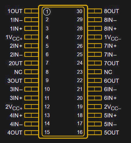
However, the largest number of op amps ever integrated into a single package is eight: until a few years ago you could get yourself an EL5811, a TL084x2, or even an LM324x2, all of which were octal op amps. The same basic circuit in each case was also available as a single, dual or quad version, so the octal op amps were really “dual quads”.
While such a thing might seem useful if you want to squeeze lots of amps in a small space, using two separate quads will give you much more flexibility when it comes to layout and routing of your circuit. We suspect that’s the reason these chips never gained much traction in the market.
Power Consumption
The classic uA741 consumes about 1.7 mA in a typical application. More modern designs have managed to reduce this: for instance, the OPA171 is compatible with the ‘741, has better performance on nearly all measures (bandwidth, slew rate, noise, offset), and uses just under half a mA. Modern circuit design techniques as well as advances in semiconductor manufacturing have enabled a way better performance/power ratio than was possible in the 1960s.
Several manufacturers have introduced op amps in the ultra-low power category, which consume less than one micro-amp. An example is the LPV801, which uses only 450 nano-amps. But the most frugal op amp on the market today is the NJU77000, which draws no more than 290 nA. To put that number into perspective, a typical CR2032 coin cell has a capacity of around 220 mAh, meaning that it could theoretically power an NJU77000 for 86 years — of course, self-discharge will drain the battery long before that. The specs of this op amp are not stellar, especially when it comes to bandwidth: a maximum of 1 kHz is way too low to process anything resembling audio, but is plenty for slow-moving circuits like gas sensors.
Output Current
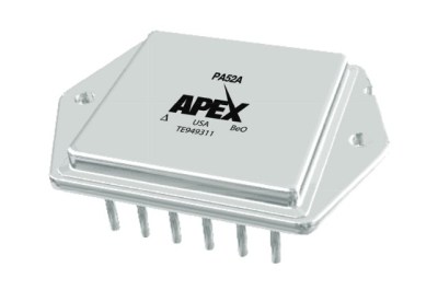
On the other end of the spectrum are power op amps that can drive large currents into a load. The classic L272, which is often used as a motor driver, can deliver a full amp on each of its two channels. But technology has moved on, and today you can buy the beefy PA50 and PA52 from Apex Microtechnology. These massive op amps can output 40 A continuously and 80 A for short periods. And although they come as a single (rather large) component, inside they are not single chips but hybrid modules: a set of integrated circuits and discrete transistors directly bonded onto a common substrate.
All this power comes at a price though; at several hundred dollars a pop, these are not your garden variety op amps. In fact, if you need more current than your preferred amplifier can deliver, it might be a better idea to make an output boost circuit using discrete power transistors. One good text on this topic is application note AN18 by Jim Williams, which demonstrates various ways to increase an op amp’s output current, voltage swing, or both.
Supply Voltage
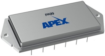
Most op amps from the earlier days could work with pretty large supply voltages: +/- 15 V was normal back in the 1970s. In today’s age of Arduinos and ESP32s, this seems excessive, and indeed many modern op amps will happily work at 3.3 V or even lower. At the other extreme however, op amps that can work at more than 100 V are also reasonably common; the LTC6090 and the ADHV4702 are examples that can work at 140 V and 220 V, respectively. But the real winner in this category is the PA99 from Apex: this op amp will happily work with 2500 V across its supply pins. It can deliver 50 mA on its output and has a gain-bandwidth product of 28 MHz. Like its high-current siblings it’s an expensive chip, at about a thousand dollars, so you’re not likely to find it in any consumer products. The main market for specialized chips like this is scientific instruments and industrial equipment using piezo actuators or electrostatic deflection.
Bandwidth
Speaking about bandwidth, which op amp is the fastest? There’s not actually a single, definitive answer to that. Let’s start by looking at the open-loop frequency response of an op amp: it’s high (more than 100 dB) at low frequencies, all the way down to DC. At some frequency, the gain begins to drop, at what we call the -3 dB point; this is where the gain has reached 70% of its DC value. The gain then continues to drop by 20 dB per decade to reach zero dB at the unity-gain frequency — zero dB means a factor of one.
In practice this means that if you configure the feedback network so that the total amplifier has a gain of one, the bandwidth of this circuit will be the unity-gain frequency. If you set it to a gain of two, it will have half the bandwidth. A gain of ten will result in one tenth the bandwidth, and so on. Since the product of the gain and the bandwidth is always the same, the unity-gain frequency is also called the gain-bandwidth product.
Most general-purpose op amps can be used at any closed-loop gain. But this flexibility comes at a price: the unity-gain frequency has to be kept relatively low to prevent oscillation. For high-speed applications you can therefore buy op amps that have been decompensated. This means that the internal circuits have been adjusted to run at a higher bandwidth, but also that the op amp cannot be used in the unity-gain configuration; the datasheet will specify a minimum closed-loop gain at which the amplifier can be used. If you don’t respect this limit, then your circuit may oscillate.
The graph below shows the open-loop gain-versus-frequency plot of a fully compensated op amp and a decompensated one. Control theory tells us that we will end up with a stable closed-loop system if we close the loop at a point where the open-loop gain drops by 20 dB per decade. (Actually, it’s more complicated than that, but we won’t go into that now.) For the fully compensated op amp this is true at any gain. But for the decompensated op amp, the gain drops by 20 dB per decade only up to a point; this is Gmin, or the minimum gain at which the amplifier will be stable. Note that the bandwidth at this point is much higher than it would have been for the fully compensated amplifier.
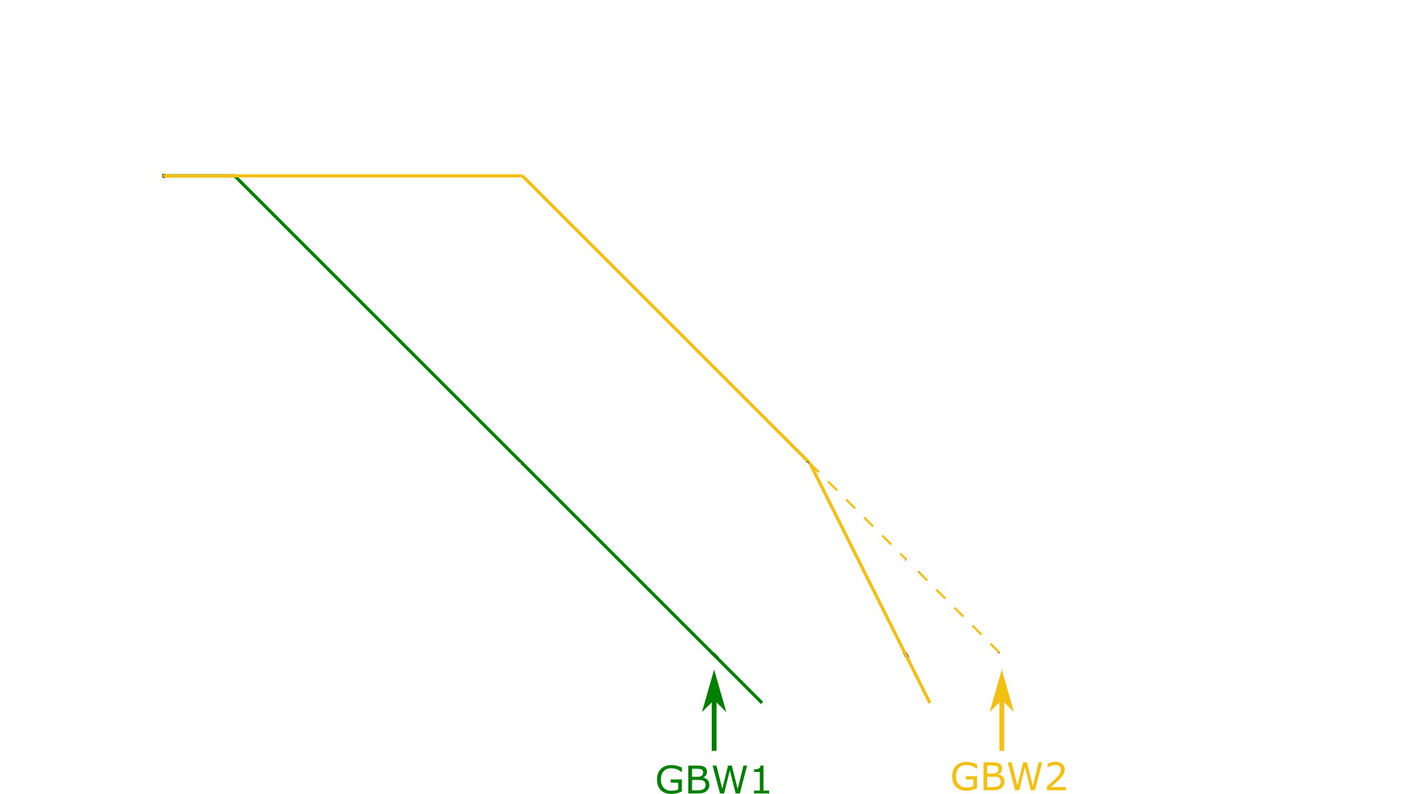
The op amp with the highest gain-bandwidth product you can buy today is the OPA855, at a whopping 8 GHz. However, because it is a decompensated amplifier, you have to use it at a gain of at least seven, in which case it will “only” reach 2.5 GHz. The fastest non-decompensated op amp is the THS4304, which can work in any configuration all the way up to its unity-gain bandwidth of 3 GHz. But before you run off and buy this chip to build a multi-GHz amplifier, remember that proper circuit layout becomes critical at such frequencies; any stray capacitance in the wrong place can upset the loop stability and turn your amplifier into an oscillator.
Slew Rate
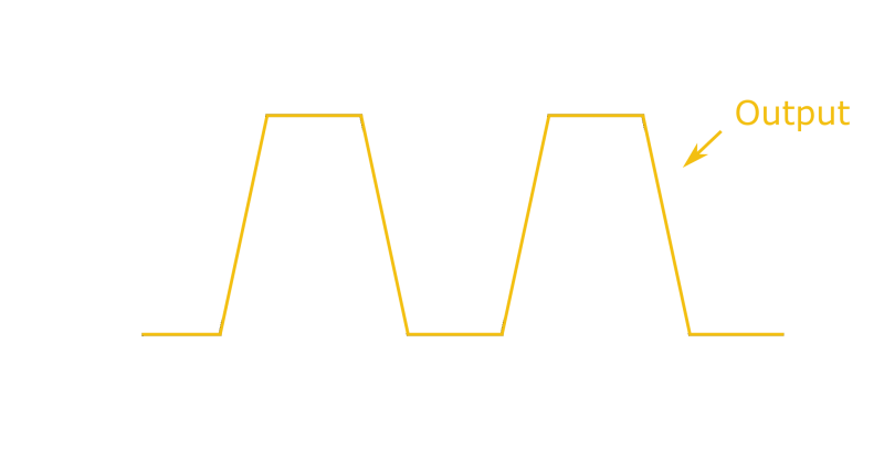
Bandwidth isn’t the only measure of speed though. Another spec that you find in any op amp’s datasheet is its slew rate. Usually measured in Volts per microsecond (V/us), it tells you exactly how quickly the chip’s output voltage can change. A simple way to measure an op amp’s slew rate is to have it output a square wave: the slope of the output’s rising and falling edges will be equal to the slew rate.
The slew rate is largely determined by the internal bias current of an op amp, and is therefore usually proportional to the supply current. Typical values range from 0.5 V/us for the uA741 to 20 V/us for the TL072. Some op amps have a clever trick inside known as slew boosting, where the bias current is temporarily increased when the op amp detects that its output can’t keep up with its input.
The highest slew rates are available in current feedback amplifiers (CFAs), which are similar to op amps in many ways but different enough that we don’t count them as such in this article. Compared to ordinary op amps, they have low open-loop gain, high input offset voltages and bias currents, and cannot be used in all feedback applications. They are commonly used in high-speed circuits where a high slew rate is the most important requirement.
Not surprising then, that the op amps with the highest slew rate combine features of CFAs and regular op amps, somewhat blurring the line between them. For example, the EL5102 has a slew rate of a whopping 3500 V/us, but a meagre 66 dB of open-loop gain where most basic op amps have 100 to 120 dB. Its input bias current is quite large as well, at 2 uA typical. The MIC920 does a bit better, but at 85 dB it’s still not a great op amp. The real winner in this category is the PA107, which can move its output at 3000 V/us but still reaches 140 dB of open loop gain. It also draws about 50 mA from its supply, so it’s not something to use when you’re designing for low power.
Unusual Materials
Nearly all integrated circuits you can buy today use silicon as their base material. A few high-speed circuits, including some of the high-speed op amps mentioned above, are made using silicon-germanium (SiGe), although this is just the top layer of a chip that’s otherwise pure silicon. Potentially, other semiconductors such as gallium arsenide (GaAs), gallium nitride (GaN) or even silicon carbide (SiC) could be used to manufacture op amps; however, given the significant cost difference with ordinary silicon these materials are mainly used for specialized discrete transistors and ultra-high speed integrated circuits.
A few research projects have shown interesting results though: The KTH Royal Institute of Technology, in Sweden, has demonstrated an op amp made in silicon carbide technology that can work at ultra-high temperatures up to 500 °C. Its performance is far from stellar, but its robustness means that it should be able to work in environments as hostile as the surface of Venus.
Here on Earth, silicon is firmly established as the semiconductor of choice, and that’s unlikely to change anytime soon. But as we’ve seen, silicon is flexible enough to enable a huge variety of op amp designs for nearly any imaginable application.


0 Commentaires