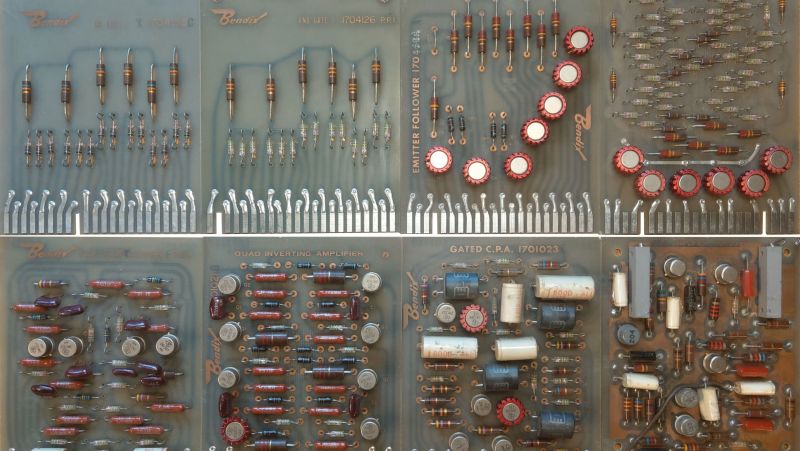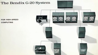
[David Lovett] aka Usagi Electric is taking a dive into yet another old computer design, this one from the early 1960s. He recently obtained eight mystery circuit boards on-loan for the purpose of reverse engineering them. It turns out these came from an old mainframe called the Bendix G-20, a successor to the 1965 G-15 vacuum tube model. The cards are:

- Full Adder
- AND Gate
- OR Gate
- Emitter Follower
- Flip Flop
- Quad Inverting Amplifier
- DLO Amplifier
- Gated CPA
Most of these are pretty straightforward to figure out, but he ran into some troubles trying to understand the full adder board. The first issue is there is some uncertainty surrounding the logic level voltages. This system uses negative voltages, with -3.5 V representing a logic 1 … or is it a logic 0? And even taking into account this ambiguity, [David] is having a hard time deciphering how the adder works. It uses a bunch of diodes to implement a logic lookup table of an adder — except he is not able to make it match any known addition scheme. [David] has called out to the community for help on this one, and if you have any ideas how this adder works, visit his wiki linked above for more information and give him shout.
We don’t know how [David] squeezes in the time for these side projects, when he is so busy on the Centurion mini-computer restoration and the monstrous single-bit vacuum tube computer he is building.
0 Commentaires