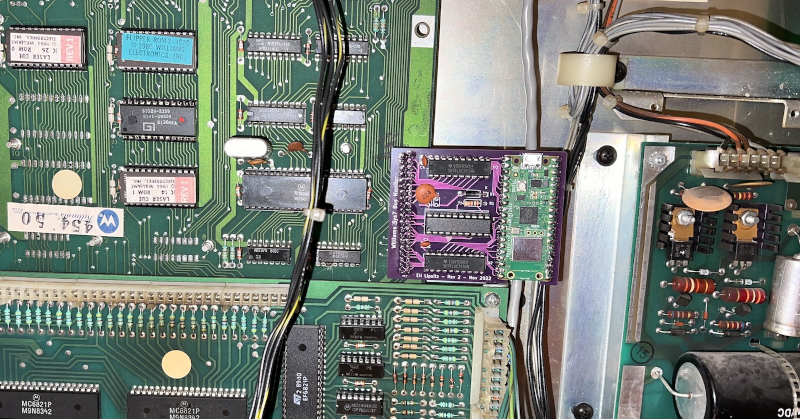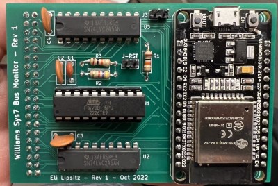
Before video games, there were pinball machines. Not that they don’t exist today, but a modern pinball machine will likely have microprocessors and other fancy things that traditional pinball machine designers could never dream of. [Eli] had one of these mechanical machines from 1974 as a kid and, later, encountered a more modern machine with a rudimentary microprocessor and other integrated circuits onboard. One thing this enabled is the ability to remember high scores. But you have to physically look at the machine, and you can only see the top four scores. [Eli] decided to adapt the machine to upload high score data to the Internet, and it is a fun project.
[Eli]’s design goals were to make it automatic and robust. That is, if the network is down or the machine loses power, you shouldn’t lose high score data. In addition, he didn’t want to change the appearance or damage the 40-year-old machine. You can see a video of how it all turned out below.
The Laser Cue machine is one of many built around the “Williams System 7” platform. A 6808 CPU, along with some I/O chips to manage all the lights, sensors, and bells. The game has only 1K of RAM, 12K or ROM, and 128 bytes (no prefix, just bytes) of RAM with battery backup. There was even a common “operating system” called Flipper ROM, and that’s actually documented over on GitHub.

Since the memory for the machine is all in external chips, it was a reasonable idea to replace the CPU with a board that monitored signals on the board. The CPU would plug into this new board, and then a newer microcontroller with an Internet connection could eavesdrop on bus traffic. However, removing the old CPU and jamming pins into the ancient socket was worrisome, so instead, [Eli] elected to tap into a test connector that was already on the board but not plugged into anything.
An ESP32 is more than capable of the speeds, although connecting to 5 V logic was a bit of a problem. The CPU has 5 V tolerant pins, but some of the 25 available pins on the development board either set items on boot or may briefly be outputs and were thus unusable. To reduce the necessary pins, [Eli] decided to do some of the decoding in separate logic. Instead of using TTL chips, he elected to use a programmable logic array.
After that, it seemed it would be straightforward, but there was something preventing the ESP32 from reading each bus cycle. [Eli] never got to the bottom of it but instead switched to the Raspberry Pi Pico W. Using the chip’s special I/O processors made the job easy, and it worked perfectly. The rest of the project was just fit and finish. Be sure to read to the end to find out the lessons learned which might help you on your next similar project.
A modern DIY machine might even have an FPGA inside. Don’t have room for a big full-sized pinball machine? No problem.
0 Commentaires