Everyone likes to play with high voltages, right?. Even though the danger of death goes up with every volt, it’s likely that a few readers will have at some time or other made fancy long sparks. You’re reading this so you lived to tell the tale, and we’d only ever counsel only doing so safely, but the point of this piece lies not in the volts themselves but in a touch of frustration at the voltage generators. There’s a circuit I see so often which annoys me every single time, so here if you don’t mind I’m going to deliver both a little rant and a look into flyback converters.
It’s Got Coils, so It’s A Transformer
How does a transformer work? An alternating current in a primary winding induces an opposite current in its secondary winding. The voltage out is equal to the turns ratio times the voltage in. Thus if you want to make a high voltage, it’s simply a case of finding a transformer with the right turns ratio, and applying the right AC to the input.
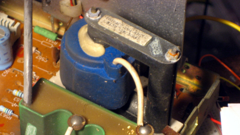
A handy choice for a high voltage transformer has been for years a TV line output transformer, also sometimes known as a flyback transformer. You could find these in CRT displays and TVs, and they consist of a square ferrite core with a big chunky high voltage overwinding for the CRT anode circuit and a load of lower voltage windings. TV designers were always out to save on parts costs, so they often had windings for all the voltage rails inside the set as well as the anode voltage, using the timebase as a crude switching power supply.
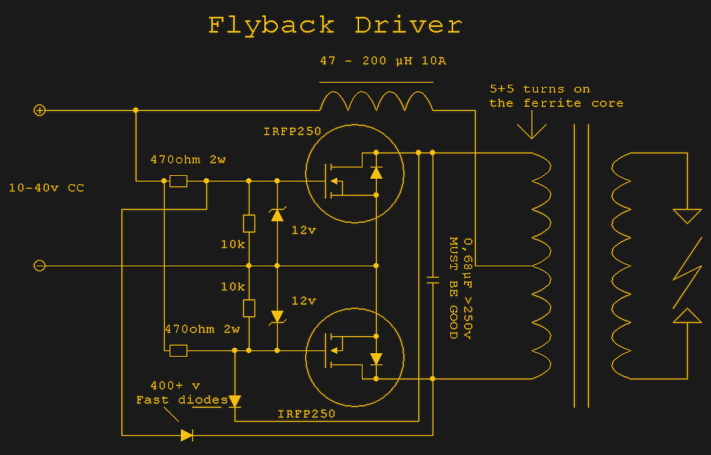
This works. It makes the volts, and we can go home happy, right? Wrong, at least if you’re me. The oscillator is an analogue circuit driving the transistor in its linear mode, and with a near 50 % duty cycle. In other words, the transistor spends roughly half its time on and half off, with a bit in the middle where it’s neither on nor off. This means it gets very hot, and you immediately need a much bigger transistor. The transformer gets hot because the core is saturating, and the whole thing takes several amps of current. it’s a great heater, but a very inefficient high voltage generator. You can even buy a module on AliExpress that’s pretty much this circuit, and I have to say right now that I hate it.
Not All Transformers Work In A Conventional Manner
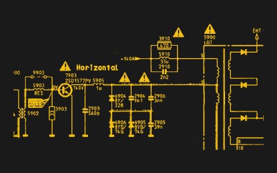
If it’s so bad then, what’s the alternative? The answer should come in looking at the circuit of the TV the transformer came from. There, a transistor switches the primary alongside a deflection coil, but it’s way more clever than a simple AC transformer circuit. It’s both a TV timebase moving the spot horizontally across the screen, and a completely different kind of power supply, a flyback supply.
When the transistor turns on, the current rises through the coils as a ramp. This provides the sawtooth required to move the dot across the screen, but it also slowly builds up the magnetic field in the transformer core. It’ll produce a voltage in the secondary, but not the big voltage needed by the CRT. At the end of the dot’s travel it needs to return to the other side of the screen, so the transistor turns off and the current in the deflection coil falls precipitously. This causes the stored magnetic field in the transformer core to collapse in a very short time, and it induces the huge voltage in that high voltage overwinding. Now a huge high voltage spike is created between the CRT anode output and ground. The CRT is designed to be a high voltage capacitor which acts as a reservoir to build up a constant DC voltage. I’ve always understood the use of the term “Flyback” to describe any supply working in this manner to refer to the period in which the dot on the CRT flies back across to the start of its next line.
My annoyance then every time I see a self oscillating converter using a flyback transformer is this: why can’t they use a flyback circuit, all they have to do is find a TV service manual or two and maybe add a 555 as a pulse generator! But aside from that, the elegant hack devised by a TV designer decades ago has of course morphed into a circuit that’s a vital weapon in the power supply designer’s arsenal. Most flyback supplies you’ll see these days aren’t used to make the huge voltages for a CRT, instead they find a place wherever a higher voltage is required than can easily be made with a boost converter. There’s a little more complexity in that the simple inductor is replaced by a flyback transformer, and if you’re paying attention it’s not quite wired as you’d expect a simple transformer step-up supply to work, but when the right magnetic is paired with the right control chip it’s an extremely efficient way to make more volts than you can otherwise get your hands on.
For their curious position somewhere between the analogue and digital worlds, switching regulators have always fascinated me. There’s no better document I can think of for anyone new to the field, and particular new to flyback converters, than Jim Williams’ 1987 app note 25 for Linear Technology: “Switching Regulators for Poets“. Enjoy making volts, and stay safe!
Header image: ZngZng, CC BY-SA 3.0.


0 Commentaires