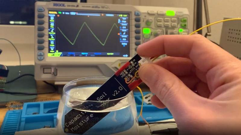
In a way, the magic of a soil moisture sensor’s functionality boils down to a simple RC circuit. But of course, in practice there is a bit more to it than that. [rbaron] explains exactly how capacitive soil moisture sensors work simply, clearly, and concisely. He also shows, with a short video, exactly how their output changes in response to their environment, and explains how it informed his own sensor design.
 At its heart, a moisture sensor measures how quickly (or slowly) a capacitor charges through a resistor, but in these sensors the capacitor is not a literal component, but is formed by two PCB traces that are near one another. Their capacitance — and therefore their charging rate — changes in response to how much water is around them. By measuring this effect on a probe sunk into dirt, the sensor can therefore indirectly measure the amount of water in the soil.
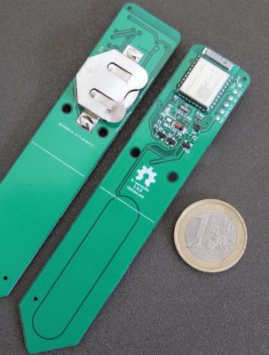
This ties into his own work on b-parasite: an open-source, all-in-one wireless soil moisture sensor (which was also a runner-up in our Earth Day contest) that broadcasts over BLE and even includes temperature readings. One thing to be mindful of if you are making your own PCBs or ordering them from a fab house is that passing current through metal in a moist environment is a recipe for oxidation, so it’s important not to expose bare traces to wet soil. A good coated PCB should avoid this problem, but one alternative we have seen proposed is to use graphite rods in place of metal.
0 Commentaires