Call us old fashioned, but we feel like when you buy a piece of hardware, the thing should actually function. Now don’t get us wrong, like most of you, we’re willing to put up with the occasional dud so long as the price is right. But when something you just bought is so screwed up internally that there’s no chance it ever could have ever worked in the first place, that’s a very different story.
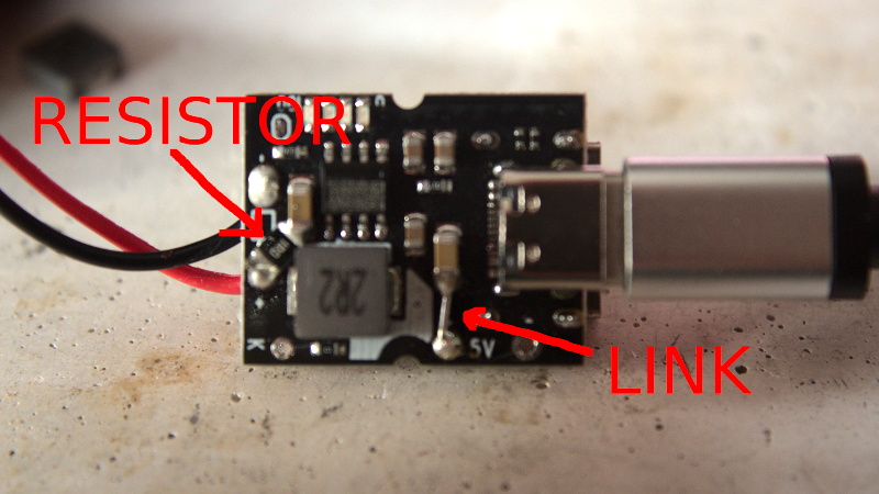
Unfortunately, that’s exactly what [Majenko] discovered when he tried out one of the USB-C power bank modules he recently ordered. The seemed to charge the battery well enough, but when he plugged a device into the USB output, he got nothing. We don’t mean just a low voltage either, probing with his meter, he became increasingly convinced that the 5 V pin on the module’s IP5306 chip literally wasn’t connected to anything.

Curious to know what had gone wrong, he removed all the components from the board and started sanding off the solder mask. With the copper exposed, his suspicions were confirmed. While they did route a trace from the chip to the via that would take the 5 V output the other side of the board, it wasn’t actually connected.
This is a pretty blatant bug to get left in the board, but to be fair, something similar has happened at least once or twice to pretty much everyone who’s ever designed their own PCB. Then again, those people didn’t leave said flaw in a commercially released module…
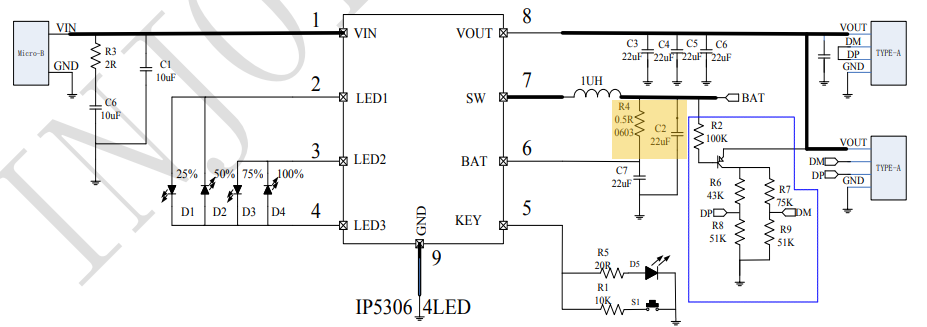
At any rate, [Majenko] just needed to solder a jumper on one of the non-sanded boards, and everything should be good to go. Well, not exactly. Adding a jumper got some power heading to the output side of the module, but only 3 V. Clearly, something else was wrong in the circuit. After some additional research and a few [BigClive] videos, he realized that some components were actually missing. Consulting the application schematic from the datasheet, it was clear that a capacitor and resistor had been left off. While the absent capacitor didn’t seem like it would be enough to cause the failure he was seeing, the resistor is supposed to be connected to the battery sense pin, and could explain why the chip wasn’t boosting the voltage.
With the resistor in place, the module started working as expected. [Majenko] notes that he still can’t get more than 1.5 amps out of these boards that are supposedly good for 2 A, but that’s another story entirely. With so many problems, it seems likely this module was a failed prototype and never meant to actually go on sale. But with part shortages ravaging the industry, it seems even the broken modules are getting pushed out the door.
Incidentally this isn’t the first time [Majenko] has tracked down some errant components in a supposedly turn-key board. Earlier this year he noticed that tweaking some of the parts used in the Raspberry Pi 4’s power supply helped reduce low-voltage warnings.


![[Thomas Sanladerer] Gets New Threads](https://lh3.googleusercontent.com/blogger_img_proxy/AEn0k_sEHAbNJC-e8OOo6L03iUGYzF7zhr5ASJWNxu9umBEOKxbUIIp9YnhT3EQBgZaYfmyHuIDrGxUH796hGiUEDdlWenuhKnNDqLBJobe4C12KM7K7Ujl6wmkzHDf1sR4YGtFHME8=w680)


![[Thomas Sanladerer] Gets New Threads](https://lh3.googleusercontent.com/blogger_img_proxy/AEn0k_sEHAbNJC-e8OOo6L03iUGYzF7zhr5ASJWNxu9umBEOKxbUIIp9YnhT3EQBgZaYfmyHuIDrGxUH796hGiUEDdlWenuhKnNDqLBJobe4C12KM7K7Ujl6wmkzHDf1sR4YGtFHME8=w100)
0 Commentaires